

The Role of Piezoelectric Stages in Optical Delay Line Devices
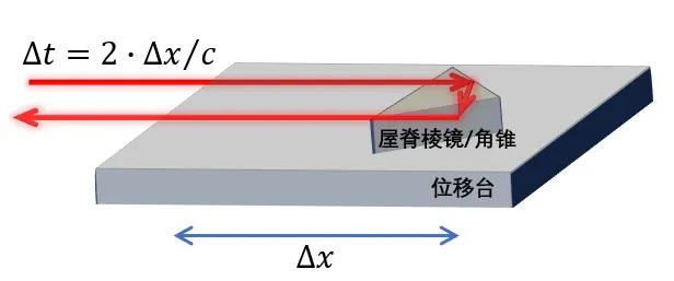
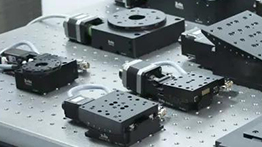
2025/04/24An optical delay line is a device that introduces a temporal delay to light, typically achieved by altering the optical path length to control the propagation time of light. A critical parameter in constructing a delay line is the scanning step size and the accuracy of each delay step. For optical delay lines built around a translation stage, the precision depends on the step size and stepping accuracy of the stage. Therefore, high-precision piezoelectric translation stages are the optimal choice. The implementation is illustrated as follows: the incident light is reflected twice by a roof prism mounted on the piezoelectric stage, returning along the original direction. The piezoelectric stage can move horizontally, introducing an optical path difference that is twice the displacement distance. The corresponding time delay is the optical path difference divided by the speed of light. This enables high-precision measurements by utilizing the time delay between pulses.
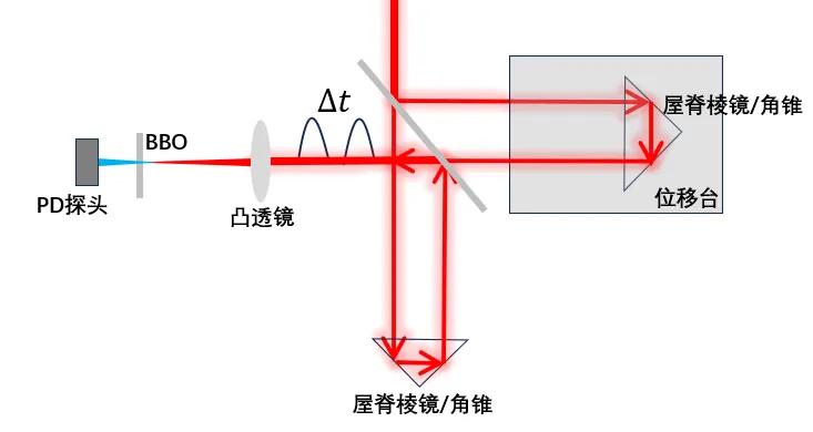
In ultrafast science, delay lines are commonly used for autocorrelation pulse width measurement, pump-probe experiments, time-domain spectroscopy, and other applications. Since femtosecond timescales far exceed the response limits of oscilloscopes and photodetectors (PD probes), direct measurement of pulse width using such instruments is impossible. Instead, autocorrelation measurement is typically employed. The principle involves splitting a pulse into two pulses of equal intensity, passing one through the delay line, and then recombining the two beams through a frequency-doubling crystal (e.g., BBO). The PD probe measures the resulting signal, which is proportional to the light intensity . By varying the time delay of the delay line (controlling the stage movement), a series of intensity-position data is obtained. Using the relation ∆t = 2∆x/c, the position data is converted into time, yielding an autocorrelation trace from which the pulse width can be determined.

Application of Delay Lines in Pump-Probe Experiments
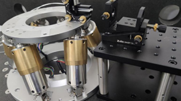
The figure below shows a pump-probe optical setup based on a Mach-Zehnder interferometer design, using annular mirrors to split and recombine wavefronts. The central portion of the input beam is reflected by a pair of right-angle mirrors mounted on a piezoelectric translation stage, serving as the delay line. The step size and accuracy of the delay depend on the performance of the piezoelectric stage. After recombination, the outer annular portion of the beam is focused into a gas jet to generate high-order harmonics. The central portion is used for probing. With this design, by adjusting the phase difference between the attosecond pulse train and the infrared fundamental laser field, sideband modulation can be observed, enabling the reconstruction of the original attosecond pulse information.
Associated application
MORE +-
High Precision Positioners: Key Enablers in 3C and Semiconductor Manufacturing Applications
High-precision positioners refer to devices that can attain positioning resolutions at the micron or nanometer scale. -
High Precision Positioners Used in the Advancing LiDAR Technology
LiDAR (Light Detection and Ranging) is an advanced remote sensing technology widely used in various fields. -
High Stability Optical Mirror Mounts: Ensuring Precise Control for Aesthetics Devices
Mirror mounts are used to adjust the light beams inside the asthetic devices -
Optomechanical Products Used in the Optical Communication Field
Optomechanical products are widely used in firber coupling, alignment. -
Role of Vibration Isolation Optical Tables in Quantum Fields
Quantum technology, the next-generation technologies.


